Laser Marking Anodized Aluminum: 7 Checks for Consistent Results
Tjxtmachine | Practical Marking Guide | November 4, 2026
Why anodized aluminum needs its own marking test
Anodized aluminum is common in electronic housings, control panels, nameplates, consumer hardware and precision components. Its appearance can be consistent across a production batch, yet two parts that look similar may respond differently to a laser. The alloy, anodizing process, coating thickness, dye, sealing treatment and surface finish all influence the final result.
This is an application guide rather than a report of a new product announcement. In a review of recent industrial laser coverage through November 4, 2026, no sufficiently verified, nonduplicative announcement offered a stronger practical topic for Tjxtmachine's customers. The useful question today is how to obtain a repeatable mark on a customer's actual anodized parts.
A visually attractive demonstration sample is not proof of reliable production marking. Buyers should define the required appearance, readability and surface integrity before selecting the laser.
1. Define the mark before selecting laser power
Start with the purpose of the mark. Is it a decorative logo, small serial number, part identification, control-panel label or a machine-readable code? Specify the smallest characters, the artwork dimensions and the expected viewing conditions.
A pale mark on a dark anodized surface may be visually striking, but its suitability depends on the customer's acceptance criteria. A code that scans once under favorable lighting is not necessarily ready for production. If formal direct-part-mark verification is required, agree on the applicable standard and verification method in advance.
For industrial identification, the most useful target is not the darkest possible mark but the required contrast and consistency without unacceptable surface damage.
2. Test the actual alloy, anodizing and finish
A marking recipe developed on one black anodized sample should not be assumed to work unchanged on blue, red or clear anodizing. The anodized layer and dye can respond differently, and some laser settings may alter the surface in ways the customer does not accept.
Ask the customer to provide production-grade samples, not just an uncoated aluminum coupon. Record the alloy, anodizing color, surface texture and any available coating specification. Test several positions and more than one part where batch variation is likely.
The production sample should match the customer's real material, color and surface finish.

3. Choose the laser source for the intended effect
A fiber laser can be suitable for many metal and anodized-aluminum marking tasks. For applications requiring more control over pulse behavior and appearance, a JPT MOPA fiber laser is a configuration worth evaluating. The final result still depends on the specific material and tested settings.
Tjxtmachine's standard 50W fiber marker uses a MAX laser source, while its 60W and 100W MOPA configurations use JPT sources. These are equipment configurations, not guarantees that a particular color, contrast or depth will be achieved on every anodized finish.
When both metal and non-metal components must be marked, UV marking may also deserve evaluation. Selection should follow the sample, not the marketing label on the laser source.
4. Adjust parameters as a controlled experiment
Laser power alone does not determine the result. Pulse frequency, pulse width where adjustable, scan speed, hatch spacing, focus position and the number of passes can all affect contrast, consistency and surface response.
Change one variable at a time or use a documented test matrix. Record the tested settings and compare samples under the same lighting conditions. Avoid copying parameters from an unrelated machine, because beam characteristics and optical configurations differ.
A repeatable process begins with recorded settings and a clearly defined acceptance sample.

5. Watch for surface damage and unintended effects
Anodizing can provide decorative and functional surface properties. Depending on the application, excessive laser interaction may alter appearance, expose underlying material or compromise a requirement associated with the finish.
Do not assume that every white, black or colored mark preserves the original protective properties. If corrosion resistance, electrical behavior, abrasion resistance or environmental durability matters, define appropriate qualification tests with the customer.
A successful laser mark must meet the product's functional requirements, not merely look sharp in a photograph.
6. Design the fixture and field around the part
The actual marking area may be much smaller than the part itself. A large enclosure with a small serial number does not automatically require a large scan field.
For small components, a stable fixture can reduce loading variation. For cylindrical items, a compatible rotary attachment may be useful, but the geometry and marking method must be tested. Marking on a curved surface without suitable positioning can affect focus and readability.
Choose the smallest practical field that covers the artwork and fixture layout while meeting the quality target.
7. Verify readability and repeatability
For ordinary logos, compare appearance, positioning and consistency against an approved sample. For serial numbers or two-dimensional codes, confirm readability with the customer's actual reader and inspection conditions.
A successful scan is not identical to formal verification. If a regulated or contractually specified quality grade is required, use the relevant verification method and suitable equipment. Tjxtmachine's standard fiber marking configurations should not be assumed to include automatic vision inspection or code grading.
Test a representative production batch rather than only the first piece. Record rejects, rework and any change in appearance across the run.
The right result is a mark that remains acceptable across real production conditions.

What buyers should send for a sample test
Send the material grade, anodizing color and finish, photos of the part, dimensions, artwork or code file, required marking area, expected production quantity and acceptance criteria. If a mark must survive abrasion, cleaning chemicals, outdoor exposure or other service conditions, include the required test method.
For a meaningful quotation, explain whether the priority is cosmetic contrast, identification, engraving depth or cycle time. These objectives can require different trade-offs.
A documented trial on the customer's own anodized parts is the most reliable starting point for machine selection.
Frequently asked questions
Can a 50W fiber laser mark anodized aluminum? Often yes, but the result must be checked on the specific anodized material. A 50W MAX configuration is not interchangeable with a JPT MOPA configuration for every appearance-sensitive application.
Does a MOPA laser guarantee color marking on anodized aluminum? No. Pulse flexibility may help with certain effects, but material, coating and settings determine what is achievable.
Can a laser mark damage the anodized layer? It can alter the surface, depending on the process. Qualification is important when protective or cosmetic properties must be retained.
Is a barcode scanner enough to verify code quality? No. Scanning demonstrates decoding under specific conditions; formal grading requires an appropriate verification procedure and equipment.
Conclusion
For anodized aluminum, equipment selection should begin with the finished part and the required result. Match the sample material, define contrast and durability requirements, compare suitable laser sources and record the tested process.
Tjxtmachine can help customers evaluate fiber and JPT MOPA marking configurations using representative workpieces. The practical goal is a stable production result—not a promise based on wattage alone.
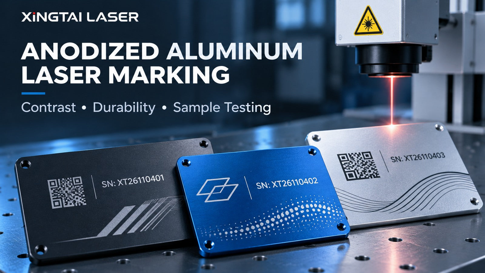
Editorial note: This is an evergreen technical application guide, not a claim about a newly announced product. Product capabilities must be confirmed through representative sample testing. Images are illustrative, not evidence of verified marks or code grades.
-
Posted in
anodized aluminum, fiber laser marking, JPT MOPA, laser marking guide